mardi 31 décembre 2019

Types of speed reducers and gear stepper motors

If we focus on their internal disposition, we can classify motor speed reducers as follows:

Planetary speed reducers
Planetary gearbox stepper motors are arranged into stages, each one having the following structure:

Sun, the central gear. It rotates around the central shaft of the system
Carrier, which holds up to 3 gears and meshes with the Sun
Ring gear, that engages with the satellites
The central shaft can also be used as a center of rotation, making it easy to switch directions.

This type of gear motor is highly reliable. It is for this reason that it is used in many automatic transmissions. In addition, it is quite versatile, which makes it ideal for many sectors – from industrial automation to robotics.


Among the advantages of planetary gear motors we can find:
Their great angular rotational stability and, therefore, their high level of precision.
Their limited vibrations when dealing with various loads
Their uniform transmission capabilities allow for a greater repeatability
One must also keep in mind that these motor speed reducers have a higher contact surface. This means that they engage more smoothly and generate lower noise levels.

This better engagement and a good torsional rigidity make this type of speed reducer more durable.Among the many types of speed reducers and gear motors, their planetary variant are more durable.(stepper precision planetary gearbox)


Worm drive
This type of industrial gear motor is simpler, since it transmits the motion of a worm wheel using an inline worm screw along its shaft.

The resulting gear ratio is calculated based on the number of teeth of the crown wheel and the indentations of the worm.

One of its greatest advantages is that it offers a high reduction with few stages, which would require several speed reductions when using conventional gears.

https://nema42motor.blogfree.net/?t=6111055
https://www.smore.com/j9fhd-stepper-articles

jeudi 26 décembre 2019

What’s the Good Point of Oyosteppers’ Linear Stepper Motors?

With the development of science and technology, automation has been applied more and more in industry. When designing automation equipment, various factors must be considered, including production line layout, installation environment, easy maintenance, transmission accuracy, wiring configuration, control system, etc. This means that it takes a lot of time to select motors and other mechanical parts and create parts lists, drawings, operations manuals and so on.

Choosing a oyostepper' linear stepper motor actuator not only provides quiet and smooth working state, but also helps engineers to provide additional benefits in the early stage of design.

IMPROVE DESIGN EFFICIENCY
linear stepper motor efficientcy
The main characteristic of automation equipment is to realize a series of basic operations such as “transmission” and “push”. In other words, you can directly select the linear stepper motors to design automation equipment, do not need to choose other drive source device, simplify the design process. Combined with the oyostepper.com’ intelligent stepper drivers, linear stepper motors can be programmed with multiple stopping points to meet the requirements of multi-station automation design. The motions are very stable when operated, even at low speeds.​

SMALL SIZE
linear stpper motor small size
The linear stepper motors is compact in structure and the minimum size is NEMA8 series, which is convenient for overall design. The motors can directly connect with the cantilever mechanism, which saves the installation space of the coupling. It makes the mechanism exquisite and simple, without intermediate transmission link, and ensures higher precision, higher efficiency and longer life.​

HIGH PRECISION
linear stepper motor high precision
Linear stepper motors adopts high-precision screw drive, the screw is made by rolling processing molding one time, the minimum linear travel per step up to 0.001524mm. In addition, it can be freely combined with the innovative Anti-backlash nuts to eliminate back clearance of transmission and achieve higher accuracy. ​

LONG LIFE
The linear stepper motors (external nut linear actuator, non captive linear actuator stepper motor)uses excellent structure design and professional motor manufacturing technology, as well as self-lubricating nuts material and high-quality screws processing technology, to provide a guarantee of high life. In fact, internal and customer test records show that some linear motors have been running continuously for more than 6,000 miles.

https://www.mapquest.com/my-maps/9472c919-db26-4d8f-b167-fece47265575
https://www.houzz.com/hznb/professionals/handyman/oyostepper-pfvwus-pf~851041382?

lundi 16 décembre 2019

Tips on How to Choose Stepper Motors for Linear Motion

Motors must accelerate loads while overcoming system friction and gravity without overheating. Here, we outline a step-by-step process for picking a motor size that’s up to the task. Key points: First define the application. Then pick the motor technology and size and go from there. Calculate velocity, reflected inertia, and reflected load at the linear actuator stepper motor input. The RMS torque requirement predicts whether the motor will work. The approach outlined here is a first-approximation analysis.

The easiest way to design a linear-motion system is to add components one by one. Then, step-by-step calculations relate input to power dissipated moving a load in a specific amount of time.Linear systems drive everything from inexpensive seat movers in passenger vehicles to precision laser cutters and CNC machines. All move loads through a linear distance in a specific amount of time.


The second and third steps of the approach outlined here are to choose the motor type and size.

One approach for designing a linear system is to list basic requirements, add components one by one, and define every force interaction along the way.

Define the problem
To begin a linear design, determine the mass of what moves and how fast it goes from A to B. We work in SI units, as they eliminate multiple conversion constants and can always convert back into English units. For example, assume we’re choosing a motor for a simple linear-rail mechanism that moves a load:

Load's mass = 9 kg

Mass orientation: Vertical

A-to-B move distance and time = 200 mm in 1.0 sec

Dwell time = 0.5 sec

Move profile = 1/3-1/3-1/3  trapezoid–controlled acceleration and deceleration

Rotary-to-linear conversion = TFE-coated leadscrew Ø8 mm and 275-mm long

Load support: Linear ball rail and TFE-coated guide rails with a friction coefficient μ = 0.01

Overall size: Limited to the smallest volume possible

Drive architecture: Must be simple, as this is a cost-sensitive application

Drive control: Four-quadrant operation with encoder feedback

Drive power supply = 32 Vdc, 3.5 Arms, 5.0 Apeak maximum output

Worst-case ambient temperature = 30°C

Because force = ma (where a = acceleration due to gravity = 9.81 m/sec2), the 9-kg mass lifted against gravity requires a force of 88 N.

Sizing: Just the beginning
This article explains how to size a motor for a relatively simple single-axis linear-motion application. What don’t we cover here?

Sizing motors for complex designs. The motor-sizing principles we outline are applicable to X-Y tables and multiaxis pick-and-place machines. However, every axis in these designs requires independent analysis of load demands.

Choosing a safety factor so the machine lasts for its intended life. A design’s number of useful cycles depends on motor size, as well as the machine’s mechanical elements including the gearbox and leadscrew assembly.

Accounting for positioning accuracy, resolution, repeatability, maximum roll, pitch, and yaw. Only linear-motion systems that account for these fully meet application requirements.

1. How much power is needed to move the load in the required time?

Calculating minimum power output to translate the load provides a starting point for specifying the rest of the system's components. For our example, this is the average power needed to lift the 9 kg from A to B in 1 sec.

Machinedesign Com Sites Machinedesign com Files Uploads 2013 08 11372 Ee Eq1

where P = power, W; F = force, N; S = linear distance, m; and t = time, sec.

Note that power calculated here is less than peak power (or instantaneous power during the move profile) to accelerate and decelerate. Likewise, power calculated here doesn’t factor in extra power to overcome system losses such as friction. We’ll calculate the motor-shaft power for that in a later step.

Pick the motor
2. What motor technology is best for this application?

As outlined in our original parameters, the final design must be inexpensive and have simple drive architecture. Stepper motors satisfy both of these requirements. However, minimizing this machine’s overall volume is also important, so a stepper isn’t recommended: The 17.64-W minimum power requirement at the load (not including system losses and instantaneous peak power) would necessitate a large stepper. A brushless motor solves the problem of design footprint, but adds cost and complicates the drive architecture.

The third option — a dc-brush gearmotor with an in-line planetary gearhead — provides a small footprint, simplified drive, and relatively low cost. Adding a leadscrew for rotary-to-linear conversion keeps gearmotor output speed at around 1,000 rpm, which reduces generated heat at the leadscrew and nut-thread interface.

Gearmotor output
3. What’s the velocity, reflected inertia, and reflected load at the gearmotor output shaft (acting as the leadscrew input)?

Step one: Calculate the peak linear velocity of the application with its 1/3-1/3-1/3 motion profile:

Machinedesign Com Sites Machinedesign com Files Uploads 2013 08 11372 Ee Eq2


where vpk = peak linear velocity, m/sec.

Step two: Calculate the minimum pitch needed to keep the leadscrew speed at about 1,000 rpm:

Machinedesign Com Sites Machinedesign com Files Uploads 2013 08 11372 Ee Eq3

where pmin = minimum leadscrew pitch, m.

For one typical product, the closest pitch in an 8-mm screw diameter is 20.32 mm.

Step three: Calculate the peak shaft speed of the leadscrew (in rad/sec) for a linear velocity of 0.3 m/sec:

Machinedesign Com Sites Machinedesign com Files Uploads 2013 08 11372 Ee Eq4

The leadscrew for stepper motor we select is TFE coated, 275-mm long, 8 mm in diameter with a 20.32-mm pitch, and paired with a freewheeling nut. Assume the leadscrew efficiency, ηs, is 86% and its inertia, Js, is 38.8 × 10⁻⁷ kg-m2.

Step four: Determine the total reflected inertia, JT, back from the load to the leadscrew shaft:

Machinedesign Com Sites Machinedesign com Files Uploads 2013 08 11372 Ee Eq5

where JL = reflected load inertia, kg-m2; m = mass, kg; and p = leadscrew pitch, m.

Step five: Determine the shaft torque needed to accelerate the load inertia Ta:

http://obd2ware.soup.io/post/677298698/Power-Off-Brakes-for-NEMA-17-and
http://blog.qooza.hk/ytobd215?eid=29195915

vendredi 13 décembre 2019

How Do Brushless BLDC Motors Work?

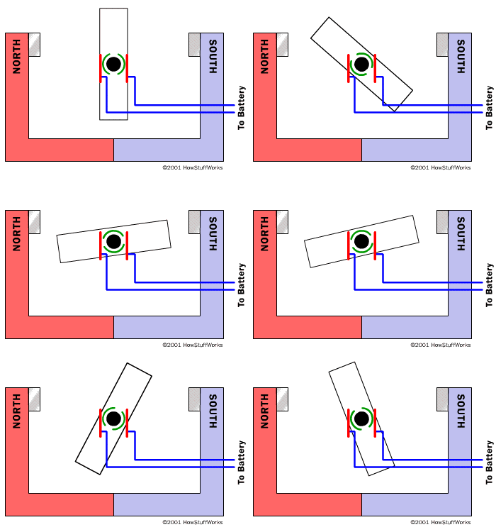
The article How Electric Motors Work explains how brushed motors work. In a typical brushless DC motor, there are permanent magnets on the outside and a spinning armature on the inside. The permanent magnets are stationary, so they are called the stator. The armature rotates, so it is called the rotor.


The armature contains an electromagnet. When you run electricity into this electromagnet, it creates a magnetic field in the armature that attracts and repels the magnets in the stator. So the armature spins through 180 degrees. To keep it spinning, you have to change the poles of the electromagnet. The brushes handle this change in polarity. They make contact with two spinning electrodes attached to the armature and flip the magnetic polarity of the electromagnet as it spins.

This setup works and is simple and cheap to manufacture, but it has a lot of problems:

The brushes eventually wear out.
Because the brushes are making/breaking connections, you get sparking and electrical noi
The brushes limit the maximum speed of the motor.
Having the electromagnet in the center of the motor makes it harder to cool.
The use of brushes puts a limit on how many poles the armature can have.
With the advent of cheap computers and power transistors, it became possible to "turn the motor inside out" and eliminate the brushes. In a brushless DC motor (BLDC), you put the permanent magnets on the rotor and you move the electromagnets to the stator. Then you use a computer (connected to high-power transistors) to charge up the electromagnets as the shaft turns. This system has all sorts of advantages:

Because a computer controls the motor instead of mechanical brushes, it's more precise. The computer can also factor the speed of the motor into the equation. This makes brushless motors more efficient.
There is no sparking and much less electrical noise.
There are no brushes to wear out.
With the electromagnets on the stator, they are very easy to cool.
You can have a lot of electromagnets on the stator for more precise control.
The only disadvantage of a brushless motor is its higher initial cost, but you can often recover that cost through the greater efficiency over the life of the motor.

For more information on brushless motors, check out the links following:https://www.oyostepper.com

Source:https://www.oyostepper.com/article-1103-How-Do-Brushless-BLDC-Motors-Work.html

What should take into considerations when choosing stepper motor

Number of wires (unipolar/bipolar)
The Duet boards use bipolar stepper motor drivers. This means you can use stepper motors suitable for bipolar drive, which have 4, 6 or 8 wires. You cannot use motors with 5 wires, because those are intended to be driven in unipolar stepper mode only. (Some unipolar motors can be made into bipolar motors by cutting a trace on a circuit board.)

Rated current

This is the maximum current you may pass through both windings at the same time. The maximum current through one winding (which is what really matters when using microstepping) is rarely quoted and will be a little higher. However, even with one winding driven at the quoted rated current, the motor will get very hot. So the usual practice is to set the motor current to no more than about 85% of the rated current. Therefore, to get maximum torque out of your motors without overheating them, you should choose motors with a current rating no more than 25% higher than the recommended maximum stepper driver current. This gives:

Holding torque

This is the maximum torque that the motor can provide with both windings energised at full current before it starts jumping steps. The holding torque with one winding energised at the rated current is about 1/sqrt(2) times that. The torque is proportional to current (except at very low currents), so for example if you set the drivers to 85% of the motor rated current, then the maximum torque will be 85% * 0.707 = 60% of the specified holding torque.
Size
There are two relevant sizes: the Nema size number and the length. The Nema size number defines the square dimension of the body and the mounting hole positions. The most popular size for 3D printers is nema size 17 stepper motor, which has a body no more than 42.3mm square and fixing holes in a square of side 31mm.

Step angle

There are two common step angles: 0.9 and 1.8 degrees per full step, corresponding to 400 and 200 steps/revolution. Most 3D printers use 1.8 deg/step motors.

Inductance

The inductance of the motor affects how fast the stepper motor driver can drive the motor before the torque drops off. If we temporarily ignore the back emf due to rotation (see later) and the rated motor voltage is much less than the driver supply voltage, then the maximum revs/second before torque drops off is.

Resistance and rated voltage

These are simply the resistance per phase, and the voltage drop across each phase when the motor is stationary and the phase is passing its rated current (which is the produce of the resistance and the rated current). These are unimportant, except that the rated voltage should be well below the power supply voltage to the stepper drivers.

Back emf due to rotation

When a stepper motor rotates it produces a back emf. At the ideal zero lag angle, this is 90 degrees out of phase with the driving voltage, and in phase with the back emf due to inductance. When the motor is producing maximum torque and is on the verge of skipping a step, it is in phase with the current.
About the Author
Established in 2010, Oyostepper.com is a professional stepper motor online china supplier at competitive prices coupled with a fast efficient service.