mercredi 7 novembre 2018

The choices among DC motors with encoders, servo motors and stepper motors

With the increasing popularity of DIY projects such as quadcopters, CNC tables and 3D printers, many people are faced with the decision of which type of motor to use in their project. For applications that require precise control of the position of the motor, the common choices are DC motors with encoders, servo motors, and stepper motors.

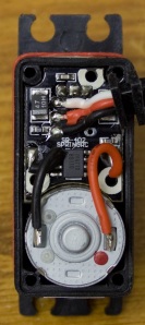
The insides of a typical servo motor. On the bottom, a 2-wire DC motor. On top, a circuit board that runs the control system and interprets servo commands.

A DC motor is the standard electric motor; it will spin as fast as it can with the DC power you provide it with. On its own, a DC motor has no position control. Most DC motor controllers allow you to change the duty cycle, a value from 0 to 100% that describes how much of your power supply is being made available to the motor.

A servo motor is just a DC motor with some upgrades: they typically have a gearbox to increase output torque, and they have a control system built right inside the motor’s casing. Since all of the control is built in, you can simply tell a servo to rotate to a specific angle, and it’ll try its best to move to that position. The downside to an integrated control system is that you usually can’t customize it in any way.

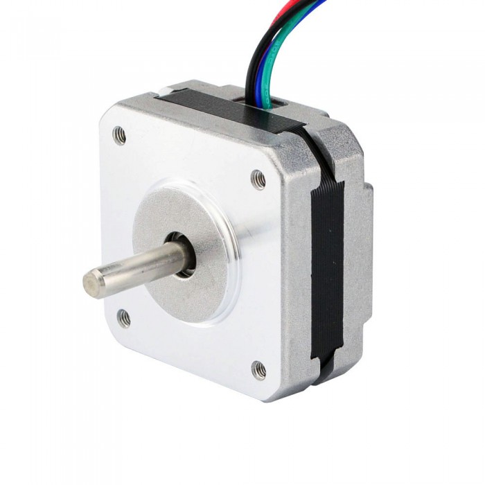
A best stepper motor uses alternating current through two separate coils to turn the rotor. I won’t go into the details, but the end result is that the motor moves in distinct “steps”, and the angle of these steps can be calculated from the step angle listed on the motor’s datasheet and the gearbox reduction ratio, if it has a gearbox. Since the motor turns a known amount each time a step is made, the position and velocity can be calculated.

1.8° NEMA 8 GEARED STEPPER MOTOR WITH PLANETARY GEARBOX
Four types of waveforms and sequences drive for stepper motors


lundi 5 novembre 2018

1.8° NEMA 8 GEARED STEPPER MOTOR WITH PLANETARY GEARBOX

Gear reduction stepper motor are perfect solutions for low speed and high torque positioning applications. GEMS provide NEMA size stepper motors that are paired with planetary gearbox and spur gearbox. Our design incorporates a square bodied motor and an round shape planetary stepper motor gearbox into a compact and cost-effective package. Our geared stepper motors are offered in six NEMA frame sizes (from NEMA 8 to geared stepper motor nema 23) and each NEMA size motor has an integrated stepper motor gearbox with a wide range of gear ratios (from 1:3.7 to 1:369) so as to deliver any desired torque and speed combinations for your applications. The dual shaft version is available for you to install the brake, shaft coupler or an encoder where you need to keep track of the shaft position. 8-lead motor is aslo available upon request for all possible wiring configurations: bipolar, unipolar, series, or parallel. For higher speed and better speed control capability, please check out our brushless gear motors.

1.8° NEMA 8 GEARED STEPPER MOTOR WITH PLANETARY GEARBOX
NEMA8 is our smallest size of geared stepper motor. The 22mm diameter planetary stepper motor gearbox has gear ratio from 1:3.7 to 1:369. The gearbox output torque is up to 143 oz-in (1 Nm)

1.8° NEMA 8 GEARED STEPPER MOTOR WITH PLANETARY GEARBOX

1.8° NEMA 8 GEARED STEPPER MOTOR WITH PLANETARY GEARBOX


vendredi 2 novembre 2018

Programming of stepping motor

The first script presented below is written for controlling our bipolar stepper motor using the Parallax Basic Stamp 2 microcontroller and the Board of education, and is best suited for demonstrating the principle of stepper motor control, however other hardware can be used with appropriate electronic modules. The nema 34stepper motor is assumed to be connected on pins 1 to 4, and 3 buttons, for changing the direction and type of sequence, are employed.

' {$STAMP BS2}
' {$PBASIC 2.5}

pulsetime CON 25 //experiment with this value in ms

buttons PIN 13
button1 PIN 14
button2 PIN 15

driveanddir VAR Nib
sel VAR Bit

driveanddir=0

DO //main loop start

SELECT driveanddir

IF (buttons=0) THEN
sel=0
IF (button1=1) AND (button2=0) THEN
driveanddir=0
ENDIF
ELSEIF (buttons=0) THEN
sel=0
IF (button1=0) AND (button2=1) THEN
driveanddir=1
ENDIF
ELSEIF (buttons=1) THEN
sel=1
IF (button1=0) AND (button2=1) THEN
driveanddir=2
ENDIF
ELSEIF (buttons=1) THEN
sel=1
IF (button1=0) AND (button2=1) THEN
driveanddir=3
ENDIF
ENDIF

CASE 0 //wave drive clockwise
DO
        driveanddir=0
        HIGH 1
        LOW 2
        LOW 3
        LOW 4
        PAUSE pulsetime
        LOW 1
        HIGH 2
        LOW 3
        LOW 4
        PAUSE pulsetime
        LOW 1
        LOW 2
        HIGH 3
        LOW 4
        PAUSE pulsetime
        LOW 1
        LOW 2
        LOW 3
        HIGH 4
        PAUSE pulsetime
LOOP UNTIL (button2=1) OR (sel=1)

CASE 1 //wave drive counterclockwise
DO
        driveanddir=1
        LOW 1
        LOW 2
        LOW 3
        HIGH 4
        PAUSE pulsetime
        LOW 1
        LOW 2
        HIGH 3
        LOW 4
        PAUSE pulsetime
        LOW 1
        HIGH 2
        LOW 3
        LOW 4
        PAUSE pulsetime
        HIGH 1
        LOW 2
        LOW 3
        LOW 4
        PAUSE pulsetime
LOOP UNTIL (button1=1) OR (sel=1)

CASE 2 //wave drive clockwise
DO
        driveanddir=2
        HIGH 1
        HIGH 2
        LOW 3
        LOW 4
        PAUSE pulsetime
        LOW 1
        HIGH 2
        HIGH 3
        LOW 4
        PAUSE pulsetime
        LOW 1
        LOW 2
        HIGH 3
        HIGH 4
        PAUSE pulsetime
        HIGH 1
        LOW 2
        LOW 3
        HIGH 4
        PAUSE pulsetime
LOOP UNTIL (button2=1) OR (sel=0)

CASE 3 //wave drive counterclockwise
DO
        driveanddir=3
        LOW 1
        LOW 2
        HIGH 3
        HIGH 4
        PAUSE pulsetime
        LOW 1
        HIGH 2
        HIGH 3
        LOW 4
        PAUSE pulsetime
        HIGH 1
        HIGH 2
        LOW 3
        LOW 4
        PAUSE pulsetime
        HIGH 1
        LOW 2
        LOW 3
        HIGH 4
        PAUSE pulsetime
LOOP UNTIL (button1=1) OR (sel=0)
ENDSELECT

Another scripting example, written in C++, for controlling the motor by using the now defunct parallel port is presented below. In this script the nema 42stepper motor is assumed to be connected on physical pins 2 to 5, or bits D0 to D3. A rapid example on how to calculate the output sent to the port:


Bit (pin) D0 (2) D1 (3) D2 (4) D3 (5) D4 (6) D5 (7) D6 (8) D7 (9)
Value (power of 2) 1 2 4 8 16 32 64 128


If you want to set a pin high, i.e. logic output 1, you need to send the corresponding value of the pin to the port. For instance for pin 5 the value to be sent is 8, for pin 3 the value is 2. If multiple pins are required to be set high, the sum of their corresponding values is sent tot the port. As an example, for pins 3 and 4 to be set high simultaneously, the value to be sent is 2+4=6, for pins 5 and 1 to be set high the value is 8+1=9.

#include
#include // ... all required libraries

#define PORT1o 0x378   //lpt output address -- check exact value in your settings
#define PORT1i PORT1o+1 //lpt input address

// ...... removed code used for defining variables and graphics drawing

//---functions defining control sequences for the motor, experiment with the delay value
void action1(void) // ----  wave drive clockwise
{
outportb(PORT1o,0);
outportb(PORT1o,1);
delay(50);
outportb(PORT1o,2);
delay(50);
outportb(PORT1o,4);
delay(50);
outportb(PORT1o,8);
};

void action2(void) // ----  wave drive conterclockwise
{
outportb(PORT1o,0);
outportb(PORT1o,8);
delay(500);
outportb(PORT1o,4);
delay(500);
outportb(PORT1o,2);
delay(500);
outportb(PORT1o,1);
};

void action3(void) // ----  full step clockwise
{
outportb(PORT1o,0);
outportb(PORT1o,3);
delay(500);
outportb(PORT1o,6);
delay(500);
outportb(PORT1o,12);
delay(500);
outportb(PORT1o,9);
};

void action4(void) // ----  full step counterclockwise
{
outportb(PORT1o,0);
outportb(PORT1o,9);
delay(500);
outportb(PORT1o,12);
delay(500);
outportb(PORT1o,6);
delay(500);
outportb(PORT1o,3);
};

// .... removed code

void main(void)  // main program loop

{
// ... removed code
}


The parallel port in brief
In a few words, the parallel port was initially designed for connecting printers to a computer but using it as a general I/O port for communicating with various other devices was pretty straight-forward, especially since IEEE 1284 standard defined the bidirectional implementation of the port. A variety of USB-to-parallel adapters are still available, a selection can be found here.

Parallel port DB-25 connector pinout
  • The data register is located at IOBaseAddress+0 (e.g. 0x378, if the LPT port address is 0x378);
  • The status register is located at IOBaseAddress+1 (e.g. 0x379) and can be accessed only through read operations;
  • The control register is located at IOBaseAddress+2 (e.g. 0x37a) and can be accessed either through write or read operations.
The lines are bidirectional and bits 4 and 5 are for internal control of the parallel interface, bit 4 validates interrupts and bit 5 validates data register input.

See more:
http://forum.cncprovn.com/threads/3967-CKD-Suu-tam-Arduino-closed-loop-Stepper-motor?p=151859

https://forum.vellemanprojects.eu/t/how-to-calculate-linear-motion-mm-with-a-stepper-motor/9660
mercredi 17 octobre 2018

Choosing on a stepper Motor for new printer

Hi,

I'm about to build my 3rd printer, even though I'm getting quite some experience already I'd like to hear some other advices regarding stepper motor.

I currently have a customized Prusa i3 printer and a customized Wilson II printer.

I currently run both printers with 0.9° step NEMA 17 motors (4200g.cm holding torque) for X and Y axis, I did run the i8 with 1.8° step NEMA 17 motors before, beside noise improvement I didn't see significant quality improvement.

Nema 17 Stepper Motor Bipolar 1.8 deg 13Ncm (18.4oz.in) 1A 3.5V 42x42x20mm 4 Wires (17HS08-1004S)

I have make numerous experiments, and I have made the following observations

Microstepping seems to have very little influence on print quality at 1/4, 1/8, 1/16 or 1/32 microsteps @ 0.9° or 1/8, 1/16, 1/32 @ 1.8° below that noise and vibration will affect the print.
the belts have a high impact on print quality, Neoprene/glass fiber belts (standard black belts) give much more vibrations than Polyurethane/steel core belts (White belts), however the later might have other troubles due to their rigidity and tension force necessary, these are the one I use on the Wilson II but I had to strongly reinforce the structure.
I have made movement tests up to 400mm/s with the Wilson II and I didn't notice losing steps (1/8 microstepping with 0.9° motors)

Now my new printer will be a different design, it'll be a 40x40x40cm 100% metal structure cube, printing platform will be moving on the Z axis and X carriage will be moving along Y axis (I considered a corexy but rejected it). Since I expect much higher rigidity than my current printers and I might want to have a heavier carriage (converting to CNC maybe), I'm thinking about using NEMA23 motors.

I have options to go with 1.8 or 0.9° motors, I can get 23HS7628 1.8°/step motors with 18.9Kg.cm holding torque , 23HS5628 1.8°/step motors with 12.6Kg.cm holding torque or 23HM1430 0.9°/step motors with 18Kg.cm holding torque. I would use TB6600 drivers at max 1/16 microstepping.

Since motor prices are quite different, I'm curious to have a second opinion. I think the 0.9° will probably not bring any quality improvement since the limitation will still be mecanical, and anyway since the motors are much stronger than nema17 I can go further in useful microstepping. I can get a sweet deal on the 12.6Kg.cm motors, and I'm hesitating with the 18.9Kg.cm ones (1.8°) which are 50% more expensive.

Or... should I just stay with cheap Nema17 motors?

Any thought?

samedi 13 octobre 2018

Control sequences of Stepping Motor

There are four types of waveforms, or sequences, through which stepper motors are driven. These are:

1. Wave drive;

2. Full step drive;

3. Half step drive;

4. Micro stepping – we will present this method and when it is employed in another article.

Wave drive
By using this method, a single phase of a nema 23 stepper motor is energized at a time. If we refer to figure 1 below we can see how a stepper motor is driven. We can observe that there are 3 phases (f=3), AA’, BB’ and CC’ and 2 teeth (z=2) North and South. The rotor will perform full steps, with the angle: Theta=360/(f*z)=60 degrees.

Control sequences of Stepping Motor


Full step drive
When the rotor of the motor depicted in figure 1 reaches position 3 we can see that the motor can also be driven by having two phases energized at the same time. The rotor will perform full steps, according to the formula above, aligning itself exactly in the middle of the angle between the stator poles, North and South. This drive method provides full torque of the motor.

The sequence will be:
AA’BB CC’
1 1 0
0 1 1
1 0 1
1 1 0


Half step drive
This method implies alternately powering either one phase or two phases at a time. The rotor will align itself either with stator poles, as in wave drive, or between them, as in full step drive. In this case the rotor will have 30 degree step angles.

The sequence is:

AA’BB  CC’
1 0 0
1 1 0
0 1 0
0 1 1
0 0 1
1 0 1
1 0 0

The direction of rotation in either case is determined on how the sequence is started. Sequences presented above assume clockwise rotation when applied starting from the first row and counter-clockwise rotation when started from back to front.

Control sequences of Stepping Motor


So, if we look at figure 1, depicting a 2-phase bipolar nema 42 stepper motor like the one we want to control, we can determine the control sequences for each method mentioned above. It can be observed that such a motor has 4 leads, corresponding to 4 pins of an output controller or interface. So the sequences will be:

• Wave drive: 1000 0100 0010 0001;

• Full step drive: 1100 0110 0011 1001;

• Half step drive: 1000 1100 0100 0110 0010 0011 0001 1001.

See more:
http://www.techsite.io/p/930613
https://yanguilai.katari.be/DcwbY8sy

jeudi 27 septembre 2018

Key features and shortcomings of Stepping Motor

Stepper motors have numerous advantages:

They ensure univocal conversion of control impulses to displacement and can be employed in open-loop control applications;
Have a wide range of control frequencies;
They provide precision and high resolution for positioning;
Allow for sudden starting, stopping or reversing without losing steps;
Can hold their position;
Are highly compatible with numerical control.
But they also have disadvantages like:

Key features and shortcomings of Stepping Motor


Fixed step value (angular displacement) for a given motor;
Relatively low speed;
Low torque;
Low power efficiency.
The characteristics of a stepper motor such as linear stepping motor or closed loop stepping motor are strongly dependent to load and type of the actuation mechanism it is employed in, so that:

A certain resolution for the complete actuation system is imposed;
Loads, forces or inertia must be reduced at the motor’s shaft;
A certain speed characteristic must be defined for accomplishing movement;
The ratio between loads reflected to the motor’s shaft and the actual torque of the motor must be kept in adequate limits.

jeudi 13 septembre 2018

Are all closed-loop stepper systems created equal?

How do I get the right control for my application?
Manufacturers apply the term "closed-loop stepper" to a wide array of controls. Here, we'll spell out how the three most common closed-loop stepper control schemes work and highlight their advantages and disadvantages.

Are all closed-loop stepper systems created equal?
No. Some manufacturers give the closed-loop stepper systems similar-sounding descriptions, which confuses the marketplace. As proof of the confusion, it's not uncommon that a designer requests one capability and actually needs another.

What are the most common closed-loop stepper systems?
There are three common types: Closed-loop stepper with step-loss compensation; closed-loop stepper with load position control; and closed-loop stepper servo control. Stepper-drive manufacturers call them all "closed loop" but the three have distinct functionalities.

What are the functionalities of these closed-loop stepper systems?
Closed-loop stepper with step-loss compensation is the most common type of closed-loop stepper control. The analog stepper driver operates as a micro-stepping drive and typically receives pulse and direction commands to move to the desired position. An encoder tracks shaft or load position. If lost steps are detected, a compensation algorithm inserts additional steps so that the motor shaft (or load) arrives at the desired position.

How do I get the right control for my application?
Machine builders must ask: Which control scheme does the application require? It may not be immediately apparent which control scheme the drive uses. Therefore, ask the manufacturer for details and review the documentation to ensure you get the right control scheme.

OYO High Torque Nema 34 Hybrid Stepper Motors TBNS001OP