The first script presented below is written for controlling our bipolar stepper motor using the Parallax Basic Stamp 2 microcontroller and the Board of education, and is best suited for demonstrating the principle of stepper motor control, however other hardware can be used with appropriate electronic modules. The n
ema 34stepper motor is assumed to be connected on pins 1 to 4, and 3 buttons, for changing the direction and type of sequence, are employed.
' {$STAMP BS2}
' {$PBASIC 2.5}
pulsetime CON 25 //experiment with this value in ms
buttons PIN 13
button1 PIN 14
button2 PIN 15
driveanddir VAR Nib
sel VAR Bit
driveanddir=0
DO //main loop start
SELECT driveanddir
IF (buttons=0) THEN
sel=0
IF (button1=1) AND (button2=0) THEN
driveanddir=0
ENDIF
ELSEIF (buttons=0) THEN
sel=0
IF (button1=0) AND (button2=1) THEN
driveanddir=1
ENDIF
ELSEIF (buttons=1) THEN
sel=1
IF (button1=0) AND (button2=1) THEN
driveanddir=2
ENDIF
ELSEIF (buttons=1) THEN
sel=1
IF (button1=0) AND (button2=1) THEN
driveanddir=3
ENDIF
ENDIF
CASE 0 //wave drive clockwise
DO
driveanddir=0
HIGH 1
LOW 2
LOW 3
LOW 4
PAUSE pulsetime
LOW 1
HIGH 2
LOW 3
LOW 4
PAUSE pulsetime
LOW 1
LOW 2
HIGH 3
LOW 4
PAUSE pulsetime
LOW 1
LOW 2
LOW 3
HIGH 4
PAUSE pulsetime
LOOP UNTIL (button2=1) OR (sel=1)
CASE 1 //wave drive counterclockwise
DO
driveanddir=1
LOW 1
LOW 2
LOW 3
HIGH 4
PAUSE pulsetime
LOW 1
LOW 2
HIGH 3
LOW 4
PAUSE pulsetime
LOW 1
HIGH 2
LOW 3
LOW 4
PAUSE pulsetime
HIGH 1
LOW 2
LOW 3
LOW 4
PAUSE pulsetime
LOOP UNTIL (button1=1) OR (sel=1)
CASE 2 //wave drive clockwise
DO
driveanddir=2
HIGH 1
HIGH 2
LOW 3
LOW 4
PAUSE pulsetime
LOW 1
HIGH 2
HIGH 3
LOW 4
PAUSE pulsetime
LOW 1
LOW 2
HIGH 3
HIGH 4
PAUSE pulsetime
HIGH 1
LOW 2
LOW 3
HIGH 4
PAUSE pulsetime
LOOP UNTIL (button2=1) OR (sel=0)
CASE 3 //wave drive counterclockwise
DO
driveanddir=3
LOW 1
LOW 2
HIGH 3
HIGH 4
PAUSE pulsetime
LOW 1
HIGH 2
HIGH 3
LOW 4
PAUSE pulsetime
HIGH 1
HIGH 2
LOW 3
LOW 4
PAUSE pulsetime
HIGH 1
LOW 2
LOW 3
HIGH 4
PAUSE pulsetime
LOOP UNTIL (button1=1) OR (sel=0)
ENDSELECT
Another scripting example, written in C++, for controlling the motor by using the now defunct parallel port is presented below. In this script the
nema 42stepper motor is assumed to be connected on physical pins 2 to 5, or bits D0 to D3. A rapid example on how to calculate the output sent to the port:
Bit (pin)
D0 (2)
D1 (3)
D2 (4)
D3 (5)
D4 (6)
D5 (7)
D6 (8)
D7 (9)
Value (power of 2)
1
2
4
8
16
32
64
128
If you want to set a pin high, i.e. logic output 1, you need to send the corresponding value of the pin to the port. For instance for pin 5 the value to be sent is 8, for pin 3 the value is 2. If multiple pins are required to be set high, the sum of their corresponding values is sent tot the port. As an example, for pins 3 and 4 to be set high simultaneously, the value to be sent is 2+4=6, for pins 5 and 1 to be set high the value is 8+1=9.
#include
#include // ... all required libraries
#define PORT1o 0x378 //lpt output address -- check exact value in your settings
#define PORT1i PORT1o+1 //lpt input address
// ...... removed code used for defining variables and graphics drawing
//---functions defining control sequences for the motor, experiment with the delay value
void action1(void) // ---- wave drive clockwise
{
outportb(PORT1o,0);
outportb(PORT1o,1);
delay(50);
outportb(PORT1o,2);
delay(50);
outportb(PORT1o,4);
delay(50);
outportb(PORT1o,8);
};
void action2(void) // ---- wave drive conterclockwise
{
outportb(PORT1o,0);
outportb(PORT1o,8);
delay(500);
outportb(PORT1o,4);
delay(500);
outportb(PORT1o,2);
delay(500);
outportb(PORT1o,1);
};
void action3(void) // ---- full step clockwise
{
outportb(PORT1o,0);
outportb(PORT1o,3);
delay(500);
outportb(PORT1o,6);
delay(500);
outportb(PORT1o,12);
delay(500);
outportb(PORT1o,9);
};
void action4(void) // ---- full step counterclockwise
{
outportb(PORT1o,0);
outportb(PORT1o,9);
delay(500);
outportb(PORT1o,12);
delay(500);
outportb(PORT1o,6);
delay(500);
outportb(PORT1o,3);
};
// .... removed code
void main(void) // main program loop
{
// ... removed code
}
The parallel port in brief
In a few words, the parallel port was initially designed for connecting printers to a computer but using it as a general I/O port for communicating with various other devices was pretty straight-forward, especially since IEEE 1284 standard defined the bidirectional implementation of the port. A variety of USB-to-parallel adapters are still available, a selection can be found here.
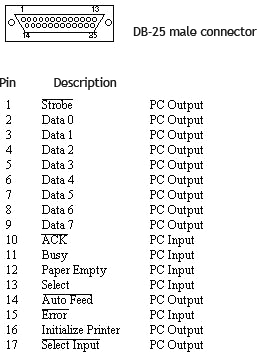
Parallel port DB-25 connector pinout
- The data register is located at IOBaseAddress+0 (e.g. 0x378, if the LPT port address is 0x378);
- The status register is located at IOBaseAddress+1 (e.g. 0x379) and can be accessed only through read operations;
- The control register is located at IOBaseAddress+2 (e.g. 0x37a) and can be accessed either through write or read operations.
The lines are bidirectional and bits 4 and 5 are for internal control of the parallel interface, bit 4 validates interrupts and bit 5 validates data register input.
See more:
http://forum.cncprovn.com/threads/3967-CKD-Suu-tam-Arduino-closed-loop-Stepper-motor?p=151859
https://forum.vellemanprojects.eu/t/how-to-calculate-linear-motion-mm-with-a-stepper-motor/9660


